How Antenna Placement Decisions Get Made Wrong on Industrial IoT Deployments — and the Cost of Getting It Right Later
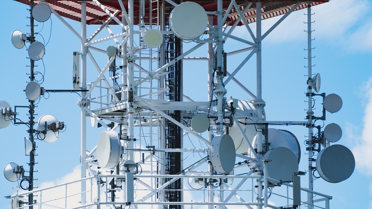
There’s a consistent pattern in industrial IoT deployments that goes wrong the same way: the hardware gets specified carefully, the SIM plan gets negotiated, the device gets installed, and then the cellular connection is unreliable. The device drops off network intermittently. Telemetry data has gaps. Remote commands don’t always get through. The engineers troubleshoot the firmware, check the carrier settings, replace the modem — and eventually, sometimes weeks into the investigation, someone looks at where the antenna is mounted and realizes it was never going to work from there.
Antenna placement in fixed industrial deployments is one of the most consequential decisions in the entire installation, and it’s treated as an afterthought more often than any other single factor that affects connectivity.
Why placement matters more than antenna spec in most fixed installations
An antenna’s gain, frequency coverage, and VSWR figures describe how the antenna performs under ideal free-space conditions. Those conditions don’t exist in most industrial environments. Metal enclosures, structural steel, equipment racks, concrete walls, and the antenna’s own mounting surface all affect the radiation pattern and the effective signal reaching the antenna.
The most common placement error in industrial deployments is mounting the antenna on the inside of a metal enclosure, or on the surface of an enclosure with the antenna pointing into the metal panel. A metal surface immediately adjacent to a cellular antenna creates ground plane reflections that distort the radiation pattern and can significantly reduce gain in the desired direction. An antenna inside a steel cabinet is operating with a Faraday cage between it and the base station — signal loss in that configuration isn’t a matter of a few dB; it can be 20dB or more, which collapses the effective range by an order of magnitude.
The fix — mounting the antenna externally with a short coaxial run through a weatherproof fitting — costs a fraction of the troubleshooting time spent after the fact. But it requires knowing this during installation planning, not after the system is in the field.
Vehicle installations and the specifics that get skipped
Vehicle-mounted cellular applications — fleet tracking, remote diagnostics, in-cab connectivity — have their own set of placement problems. The correct mounting position for a roof-mounted antenna on a vehicle is toward the center of the roof, away from the edges. The vehicle roof acts as a ground plane that benefits the antenna’s pattern; mounting near the edge reduces the effective ground plane area and degrades performance in directions away from the vehicle center.
Through-hole (NMO) mounts provide a solid mechanical connection and good ground plane contact. Magnetic mounts are convenient for temporary installations but should not be treated as permanent solutions — they rely on contact pressure for the ground plane connection, and vibration over time degrades that contact. A magnetic mount that tested fine in a parking lot may have intermittent ground plane contact after six months of road vibration.
Cable routing matters too. A coaxial cable with a tight bend radius near the connector introduces impedance mismatch and signal loss. In a vehicle, cables are often routed through door seals, under trim panels, and through tight spaces. Every 90-degree bend in a coaxial cable is a potential loss point if the bend radius isn’t maintained. This is particularly true for thinner, more flexible cables that trade bend tolerance for minimum loss — the cable choice and the routing plan need to be made together.
Outdoor fixed installations: what changes when the environment does
Outdoor cellular antennas for fixed infrastructure — remote monitoring stations, agricultural IoT nodes, industrial equipment in open facilities — face different problems than indoor or vehicle applications. The antenna itself may be fine, but wind loading, thermal cycling, UV exposure, and moisture ingress at connectors all degrade performance over time in ways that aren’t visible without physical inspection.
Connector weatherproofing is regularly underdone. An SMA or N-type connector exposed to outdoor conditions without self-amalgamating tape or a proper weatherproofing boot will eventually allow moisture ingress into the coaxial cable. Water in a coaxial cable doesn’t produce obvious failure — it produces gradual signal degradation over months as the dielectric absorbs moisture and the cable loss increases. A system that worked fine at commissioning starts dropping out the following winter, and the cable is the last thing anyone checks.
Antenna orientation matters in ways that aren’t obvious on a spec sheet. An omnidirectional antenna’s radiation pattern assumes the antenna is vertical. Mounted at an angle — because the available structure wasn’t perfectly vertical — the pattern tilts, and the coverage footprint changes. For a deployment where the base station is in a known direction, a tilted omnidirectional antenna may have meaningfully less signal toward the base station than the same antenna mounted correctly.
The cost calculation that changes the conversation
The incremental cost of getting antenna placement right during initial deployment is modest: a slightly longer coaxial cable run, an external mounting bracket, a few minutes of additional planning during site survey. The cost of correcting a placement mistake after deployment depends heavily on access — for a device in an accessible indoor location, it might be an hour of labor. For a remote monitoring node on an offshore platform, a wind turbine nacelle, or a piece of mining equipment, a technician dispatch can run into thousands of dollars per site, multiplied by however many units in the deployment have the same problem.
This is why antenna placement deserves the same attention in the design review as the antenna specification itself. A 4g lte antenna with strong IP ratings and wide temperature tolerance does its job reliably only when it’s installed where the RF environment allows it to. The hardware specification and the installation specification are both part of the same decision.
Deployments that perform consistently from day one share a common characteristic: the people specifying the hardware also thought through where it would be mounted, how the cable would be routed, and what would be adjacent to the antenna in the installed position. That’s not a complicated process. It just needs to happen before the install truck leaves, not after the first service call.